


Why Solder Joints Crack on Electronic PCBs
Author Dmitrii KhramtsovPosted 12 September 2024
Updated 4 February 2026

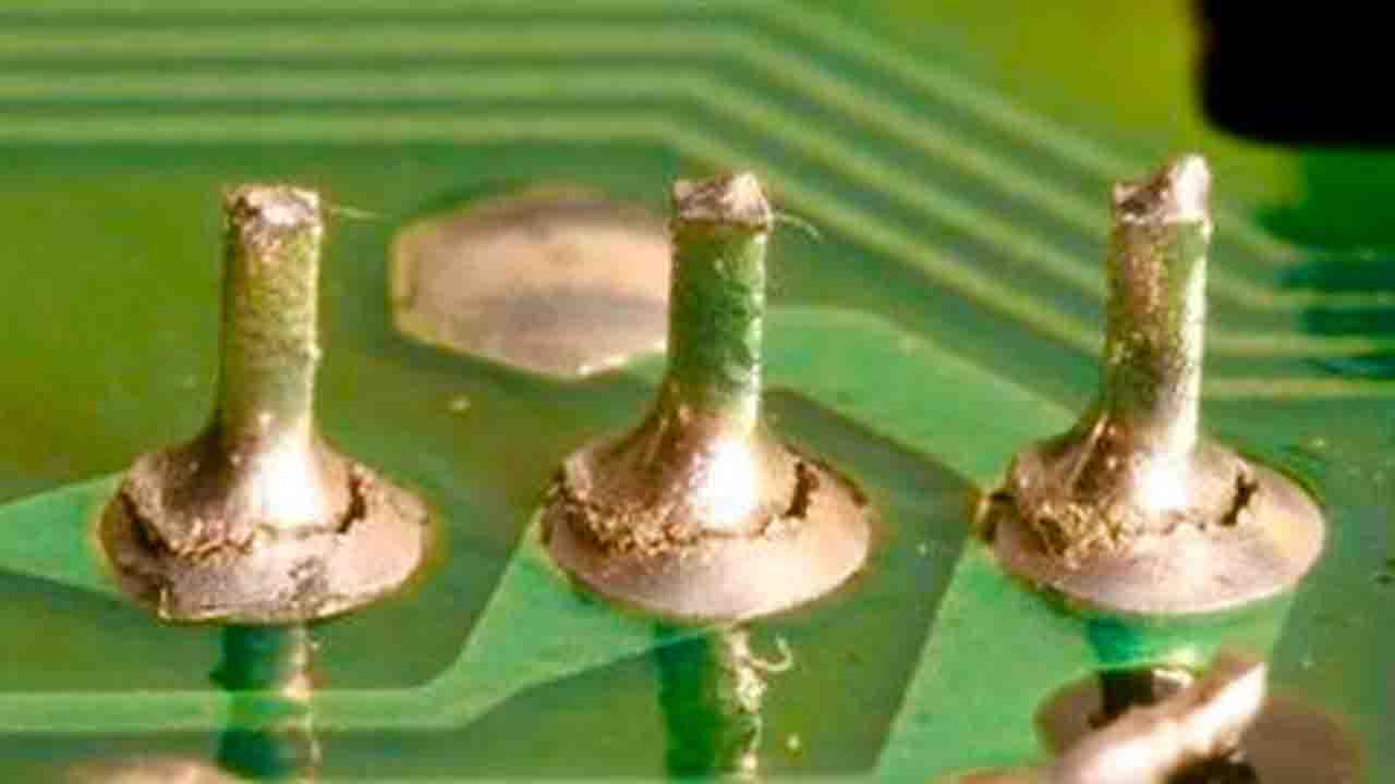
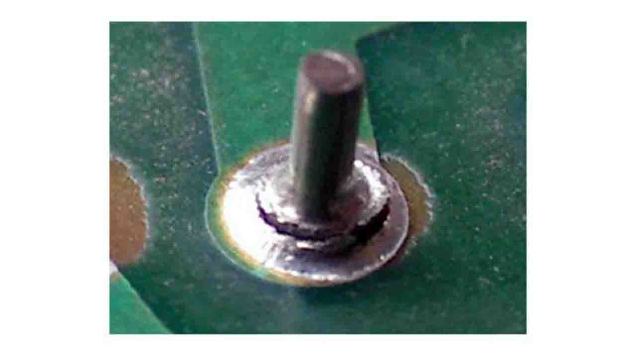
Many of you have encountered cracks in solder joints on printed circuit boards — especially on through-hole DIP components. A PCB may operate for years and then suddenly fail because of cracks in the solder joints.
Why solder joints crack over time, and what combination of factors leads to this. How to reduce the probability of cracks in solder joints if you are involved in electronics design, manufacturing, or PCB repair.
Vibration Impact on Solder Joint Reliability
Absolutely everything vibrates in our world, and in the context of soldering and printed circuit board reliability, vibrations have a very clear significance.
Electronic devices are used almost everywhere and are constantly exposed to vibrations, dynamic loads, impacts, and mechanical deformation. Over time, vibrations weaken solder joints, especially in through-hole components where mechanical flexibility is present. Metals in the soldered area gradually lose bonding strength, and sooner or later a crack can form in the solder joints.
In industrial electronics, the effects of vibration and component movement are reduced by fixing the component body with adhesive at three or four points, or under heavy SMD component. The vibrations experienced by a solder joint are closely related to the next factor -
Components weight and miniaturization
The smaller the electronic component, the lower the mechanical load on the solder joint – that’s the rule.
I understand that it is not always possible to replace large film capacitors to compact SMD capacitors. However, during PCB design, it makes sense, whenever possible, to look for solutions that allow the use of smaller smd components instead of massive through-hole DIP components. Component weight directly affects the level of mechanical stress, sensitivity to vibrations, and long-term solder joint fatigue. The next factor is -
Current and High voltage
The currents and high voltages passing through the soldered metals have a significant impact on the durability of the soldered joints. At the solder joint, three different materials are present at once — the component lead metal, PCB copper, and the solder alloy. These materials have different densities, structures, and physical properties.
During long-term operation under electrical load, electrical and thermal effects accelerate joint degradation, especially when combined with other factors. The currents and high voltages are not the only cause, but it is an important part of the overall picture.
Solder Alloy and Soldering Quality
Soldering quality directly affects the reliability of solder joints. Insufficient solder volume, small fillets, pores, and voids inside the solder joints — reduces the mechanical strength of the solder joints.
Solder quality also matters. Using solders from reliable manufacturers reduces the likelihood of hidden defects and unstable PCB behavior over time.
Even the design of PCB pads plays a role. Insufficient pad size for high currents or voltages can become an additional source of crack formation in combination with the previously mentioned factors. And right now, next factor -
Flux and soldering temperature
Flux has a major influence on solder joint quality — as a standalone flux and as part of solder wire. High-quality soldering flux and properly selected soldering temperature ensure good wetting and flow of the molten alloy; also allow solder to fill micro-voids; also reduce of micro-defects in the solder joint.
I have a separate articles on the bottom of this page, dedicated to soldering temperatures, soldering iron tip temperatures, what is the soldering flux. And next cause -
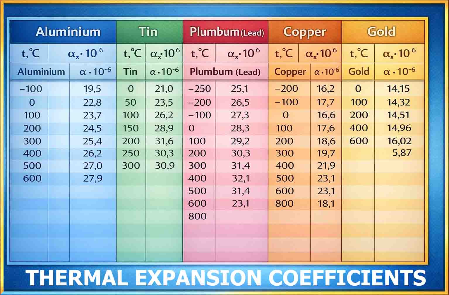
External temperature fluctuations coefficients
Sharp and cyclic temperature changes significantly reduce the shelf life of electronics. Different metals have different coefficients of thermal expansion, and this is especially important in solder joints.
Look at the table of thermal expansion coefficients of metals most commonly used in electronics. Even in the range from 0 to 100 °C, their ranges are very different.
Example 1
When heated, copper with a thermal expansion coefficient 16.6 and tin with a coefficient of 23.4 expand differently. This creates internal stresses that can lead to microcracks over time.
Example 2
An aluminum component lead soldered with leaded alloy, forms a joint with different expansion coefficients, increasing the risk of cracking.
At the interface between solder and metal, stress occurs during every heating and cooling cycle, and one material always expands slightly more than the other.
Preventing crack formation in soldered joints
All factors — vibrations, component weight, electrical load, soldering quality, soldering materials, and temperature fluctuations — work together, not separately. Design your PCBs with the thermal and mechanical properties of materials in mind.
The smaller the electronic component, the lower the impact of thermal expansion and vibrations. For large and heavily loaded components, a different strategy is used — improving component quality, proper fixation, and correct selection of soldering materials.
Thank you for reading!
Watch video Why Solder Joints Crack on PCBs